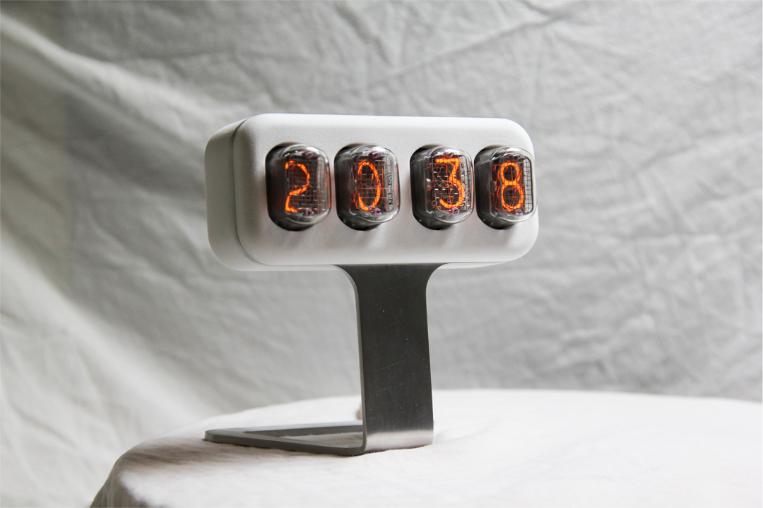
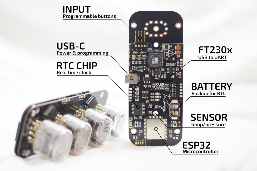
The NIXLER comes pre-programmed with the following 3 modes
Mode 1:
Display time on the four nixie-tubes. This mode alternates between displaying current hour and minute (hh:mm) and second (xx:ss). The time is displayed in either 12 or 24 our format. This mode is also called “standby mode”.
Mode 2:
From standby mode by toggling one of the buttons you can cycle through different sensor data. By toggling button 1 (the top button) you can cycle through and display temperature (C or F), pressure (KPa), date/month and year.
Mode 3 (Setting Mode):
In order to set and adjust time, date, month year and other settings including temperature mode (fahrenheit or celsius), 24/12 hour mode and LED backlight color, the following steps should be followed.
Enter setting mode:
In order to enter setting mode hold down both buttons until all 4 nixie-tubes start alternating between the numbers 3 and 0. Release the buttons when this happens. You are now in setting mode.
- Set hour:
The two leftmost nixie-tubes now light up. Adjust the HOUR by pressing button 1.
(The time is adjusted in 24h mode.) - Set minutes
Press button 2 in order to set the HOUR and switch to MINUTES. Use button 1 to cycle through minutes.
- Set 12/24 hour mode:
Press button 2 for the next setting: The two middle nixie-tubes now lights up. Use button 1 to cycle between 24 and 12. this sets the clock mode to either 24 hour or 12 hour.
- Set date:
Press button 2 for next setting: The two leftmost nixie-tubes now light up. Use button 1 to set the date (1-31).
- Set month:
Press button 2 for next setting: The two rightmost nixie-tubes will also light up. Use button 1 to set the month (1-12)
- Set year:
Press button 2 for next setting: The leftmost nixie-tube now lights up. Use button 1 to cycle through the digits and set the year (2020). Use button 2 to jump to the next digit.
- Set fahrenheit or celsius:
When all 4 digits in the year is set, press button 2 to get into the fahrenheit or celsius setting. The two middle nixie-tubes now light up. Use button 1 to toggle between 1-1 and 2-2 being displayed on the nixie-tubes. 1-1 indicates celsius while 2-2 indicates fahrenheit.
- Set tube saving mode*:
Press button 2 to go to the next setting. The two middle nixie tubes lights up. Use button 1 to toggle between 0-0 and 1-1. 1-1 indicates tube saving mode ENABLED and 0-0 indicates mode DISABLED. The “tube saving mode” automatically turns off the nixie tubes during the night from 1am to 7am.
- Set background LED color:
Press button 2 to go to the next setting: The NIXLER now shows 9-9-9-9 on all the nixie-tubes. Use button 1 to toggle between the possible LED background colors (a no color option is also available here). press button 2 to exit setting mode. The NIXLER should blink twise with a white light in order to indicate exit setting mode.
* Tube saving mode is only available on units shipped after 31st of January 2021 (software version 1.1).
DIY hacks and Development Resources
The NIXLER is designed to be open source with the developer and creatives in mind. The simplest way to customize and upload new code is through the Arduino Integrated Development Environment (IDE). This section gives some useful information and resources, and a 4-step introduction guide on how to get started.
Content:
1. Reset and Boot button access
2. Download Arduino IDE and default NIXLER code
3. Install ESP32 board and libraries in Arduino IDE
4. Upload Code
5. Circuit Schemtatics
6. Comments and Questions
1. Reset and Boot button access
In order to upload new code to the NIXLER you need to open the casing and access a RESET and BOOT button.
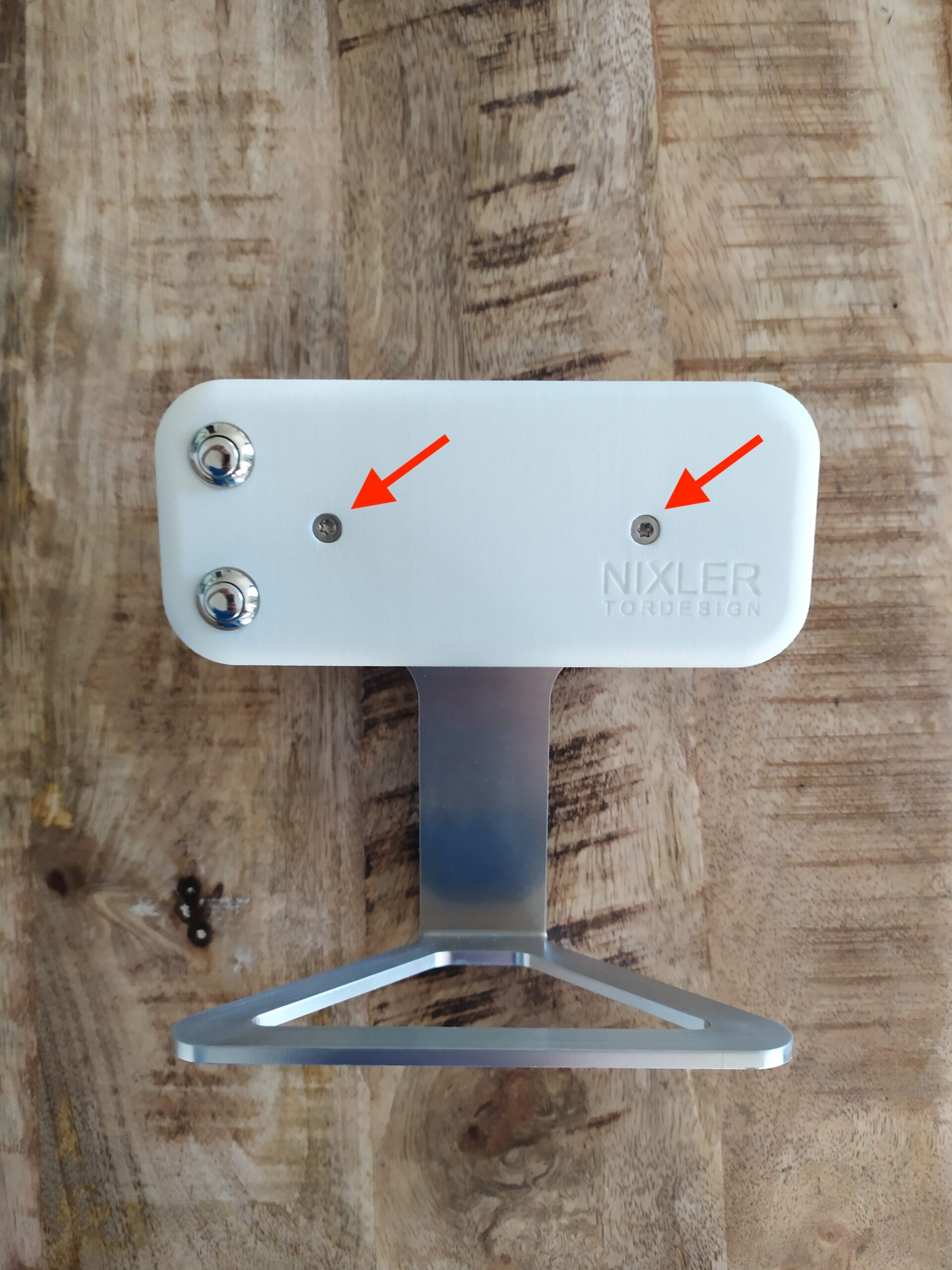
Remove the two screws from the casing using a torx T-10 bit (a 2mm hex driver will also do) and remove the casing by tilting it as shown in the following pictures. Be careful to not bend the USB-C connector.
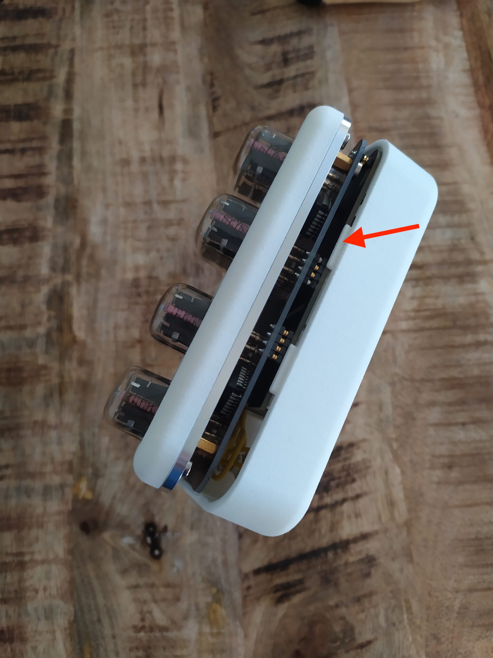
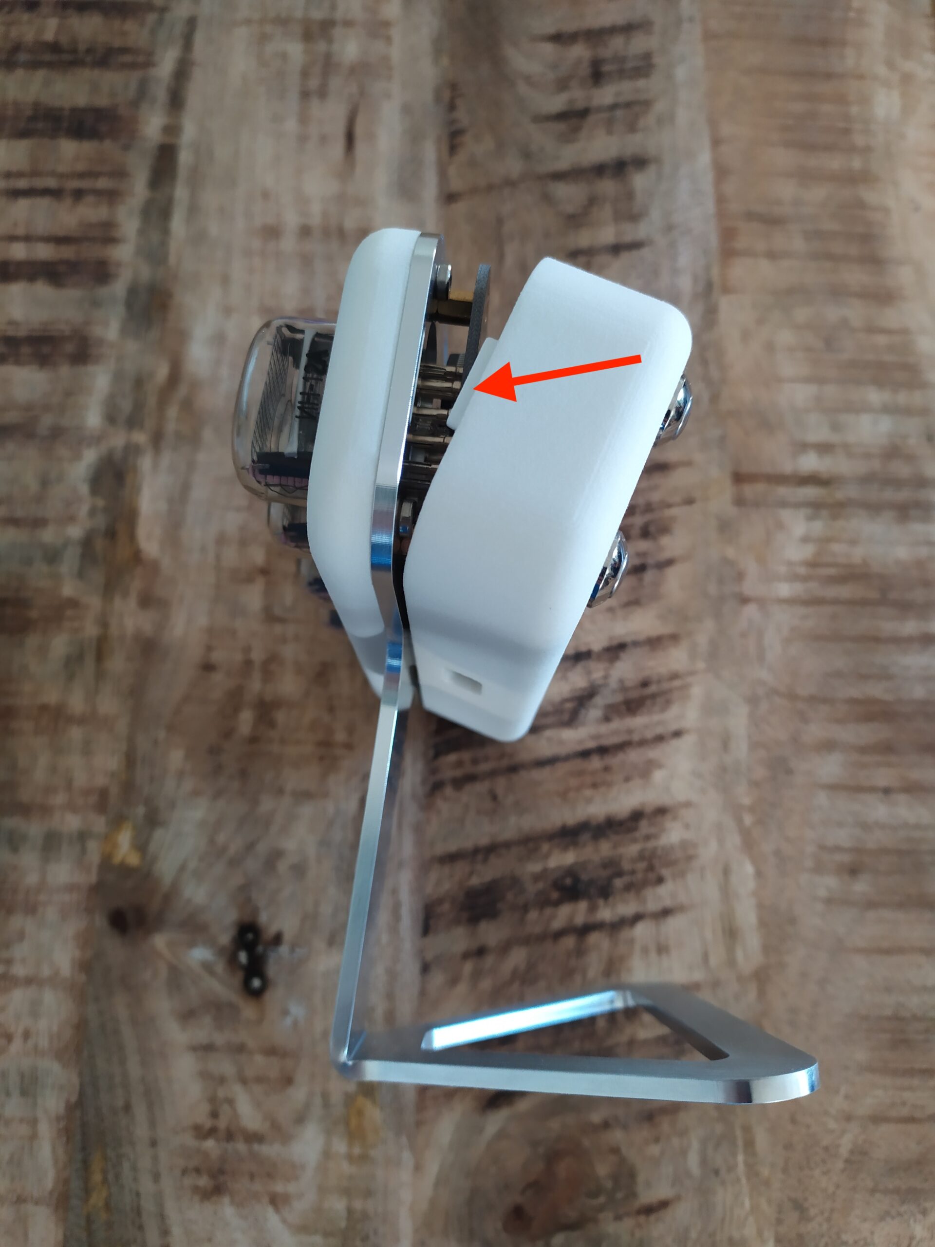
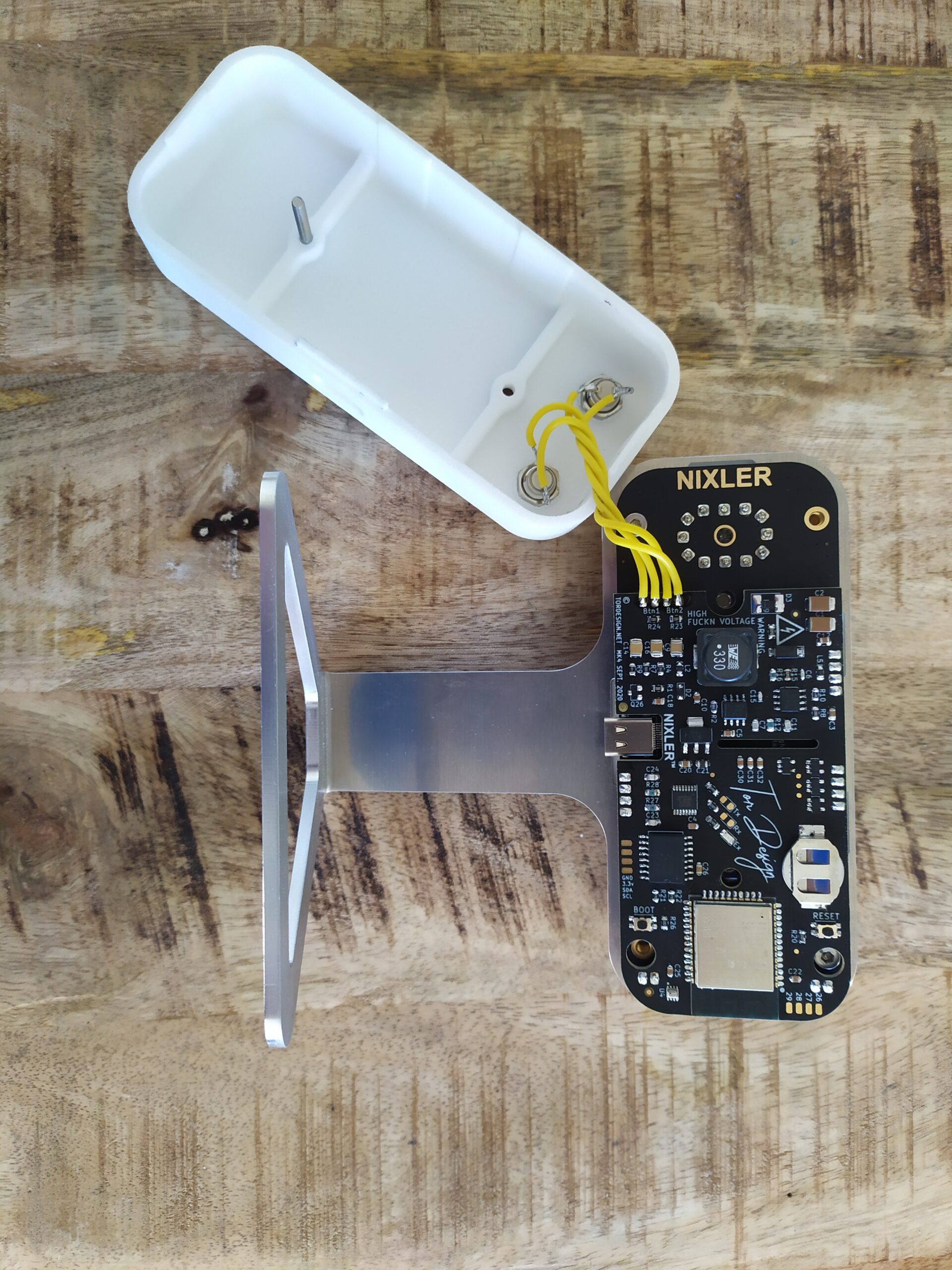
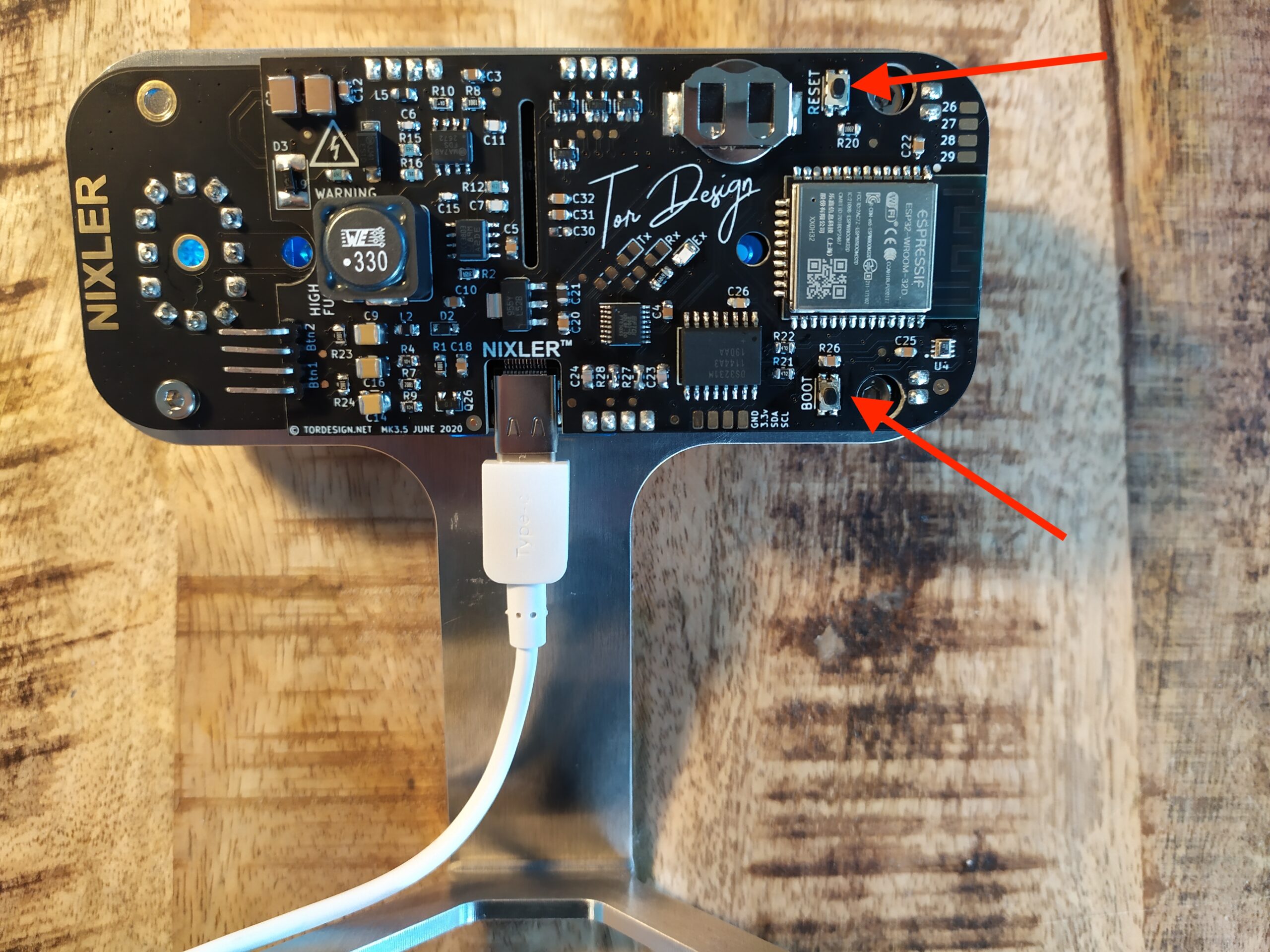
Now that the RESET and BOOT buttons are accessible we are ready to get the ESP32 chip into boot mode.
In order to set the ESP32 chip into boot mode holdt down the BOOT button while pressing the RESET button. Next let go of the RESET button again before letting go of the BOOT button. The board is now ready for code upload. Press the RESET button again when code is finished uploading.
2. Download Arduino IDE and default NIXLER code
In order to compile and upload new code we can use the Arduino development environment. Head over to the Arduino page and download and install the latest version (tested and nominal operation on version 1.8.13) https://www.arduino.cc/en/software
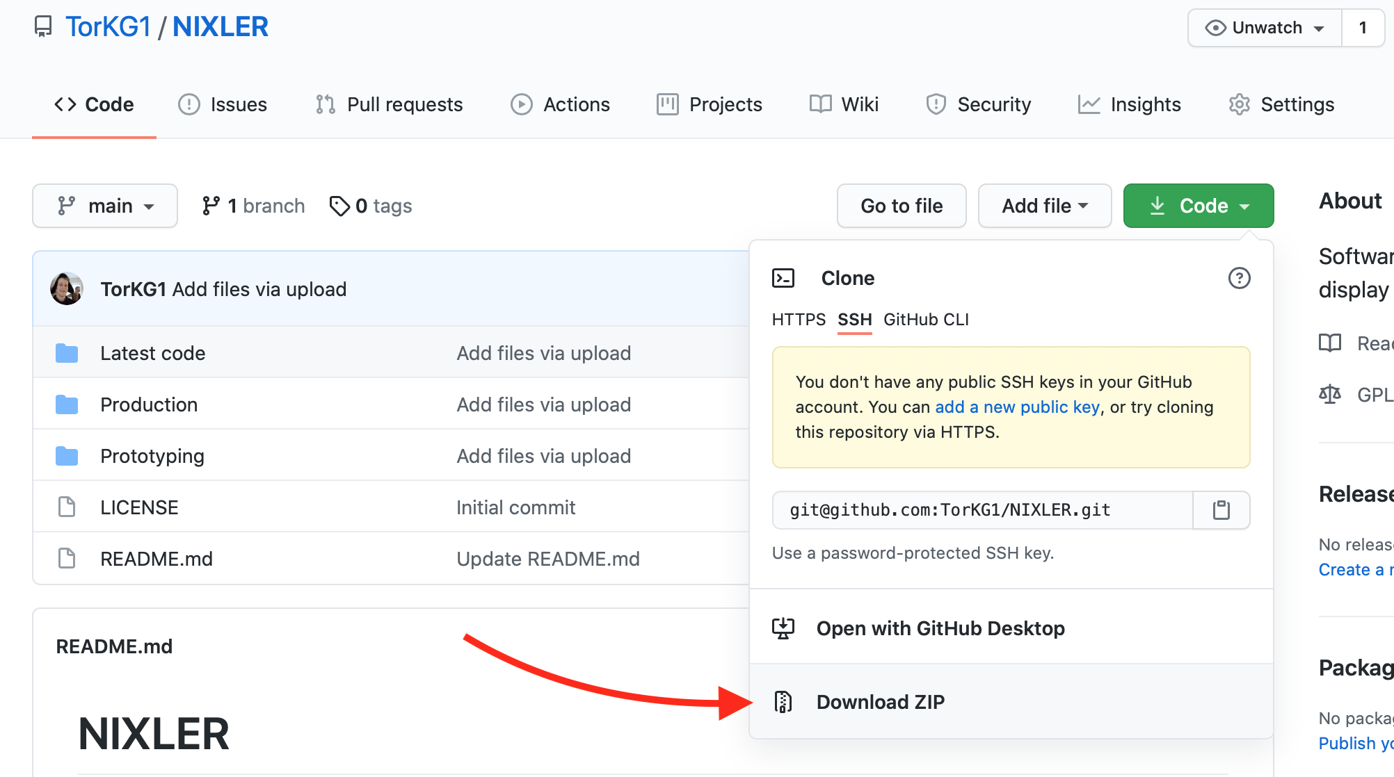
Next you will need the default code that ships with the NIXLER. This is a good starting point for customizing and implementing your own solutions. The lates working code is found on the github repository page under the folder “Latest code”.
Download and unzip the repository to somwhere you remember.
click here to go to the latest source code
3. Install ESP32 board and libraries in the Arduino IDE
When the Arduino IDE is installed we need to install the “board type” (support for the microcontroller used inside the NIXLER) and a few libraries used in the default NIXLER code.
However first you can try opening the default code downloaded in step 2.
Navigate to the master folder and open the latest version in the “Latest code” folder (filename: TD_NIXLER_V_1_2.ino).
Next If the ESP32 board is not already installed we need to get this sorted. We do this with the following two steps:
In the Arduino IDE top menu go to ->Arduino-> Preferences and add the following URL in the “Additional Board Manager URLs” window: https://dl.espressif.com/dl/package_esp32_index.json
If this window is already populated with other URLs simply sepparate multiple URLs with a comma.
In the Arduino IDE top menu go to ->Tools-> Board -> Board Manager and search for “ESP32“. Install the latest version from Espressif Systems.
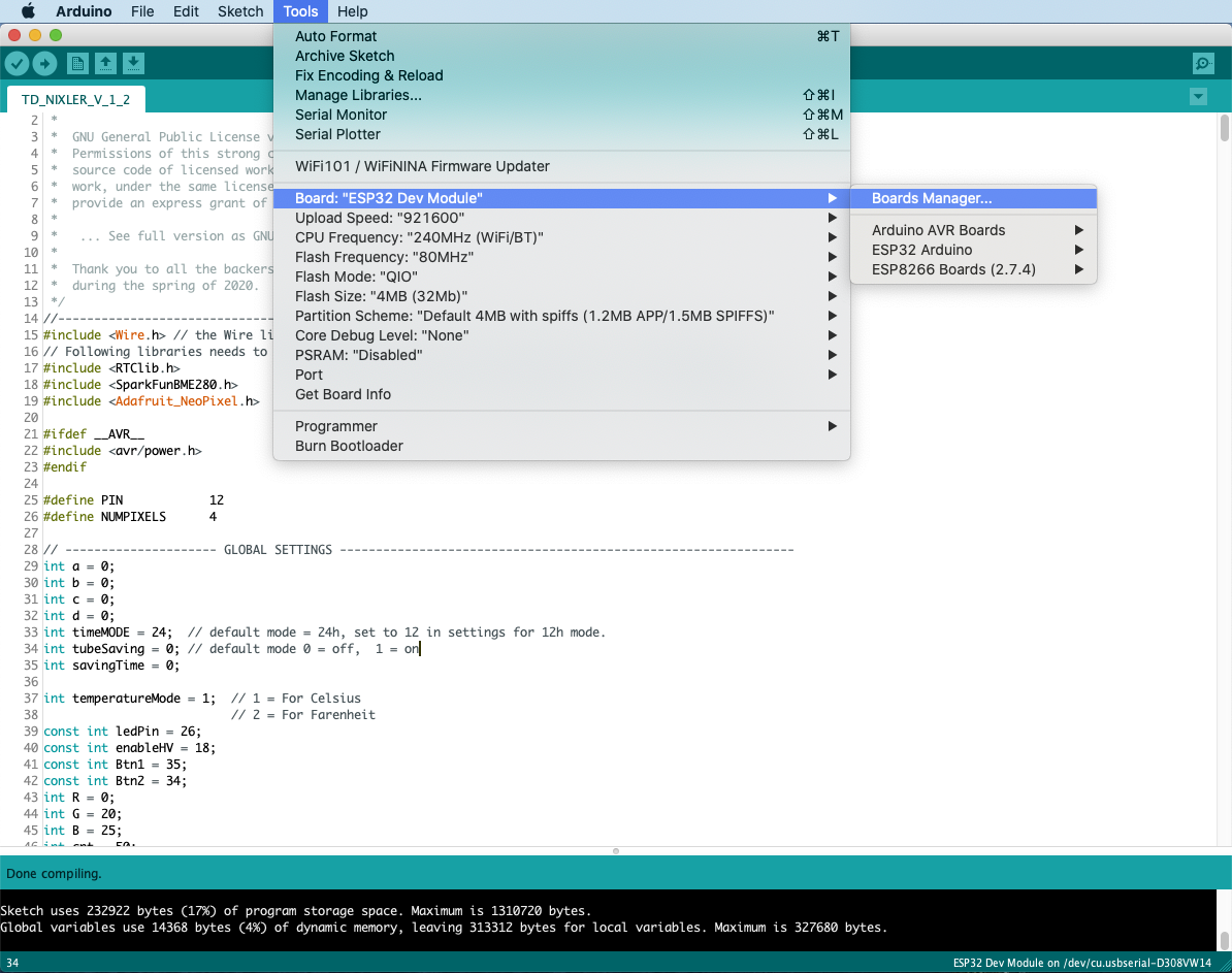
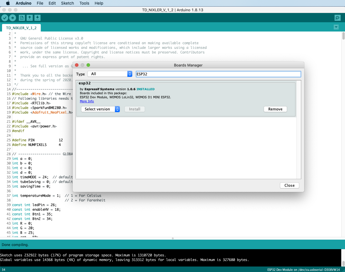
Now that the ESP32 board is installed make sure that you choose the “ESP32 Dev Module” as the board type. Leave the other options like: Upload Speed, CPU frequency etc. as is. However before uploading any code you need to choose and select the NIXLER in the “Port” option.
Make sure that the NIXLER is connected to your computer using a sync cable. Under the Port table you should see something like “usbserial-D308VW17” as shown in the following picture. This is the name of the USB to UART chip on the NIXLER. Seeing this name means that the computer recognises the connected peripheral. (If this is not showing up, step 1 is to secure that your cable is properly connected and that you are using a sync cable. step 2 install a driver for the FT230x USB to UART chip).
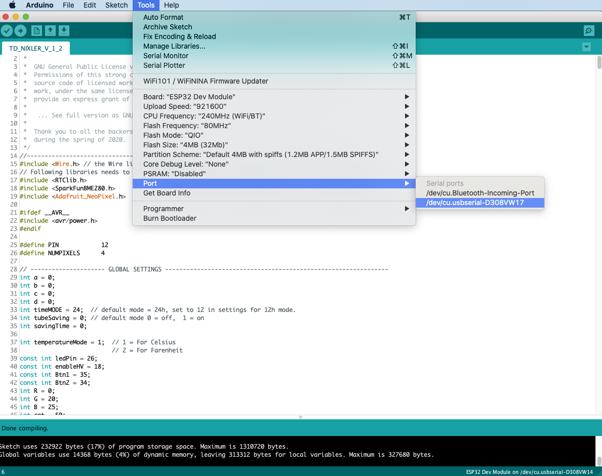
You can now compile and verify the code by clicking the verify button in the upper left corner of the Arduino IDE. If you get an error of missing libraries you will need to install the libraries as described in the code from line 15 to line 19. This is fairly easy and can done from within the Arduino IDE, just follow the description in the code.
4. Upload code
When the libraries are installed you should get a “Done compiling” message when clicking the verify button.. thada! you are now ready to upload code to the NIXLER! Remember to do the boot routine with the exposed buttons on the back of the display circuit board before clicking upload.
Happy coding and customizing!
If something in this guide is unclear or you find yourself stuck
please leave a comment at the bottom of this page.
If you have some fixes or cool new functionality you want to add and share,
go ahead and fork the master branch and add a pull request on github.
Cheers! 🙂
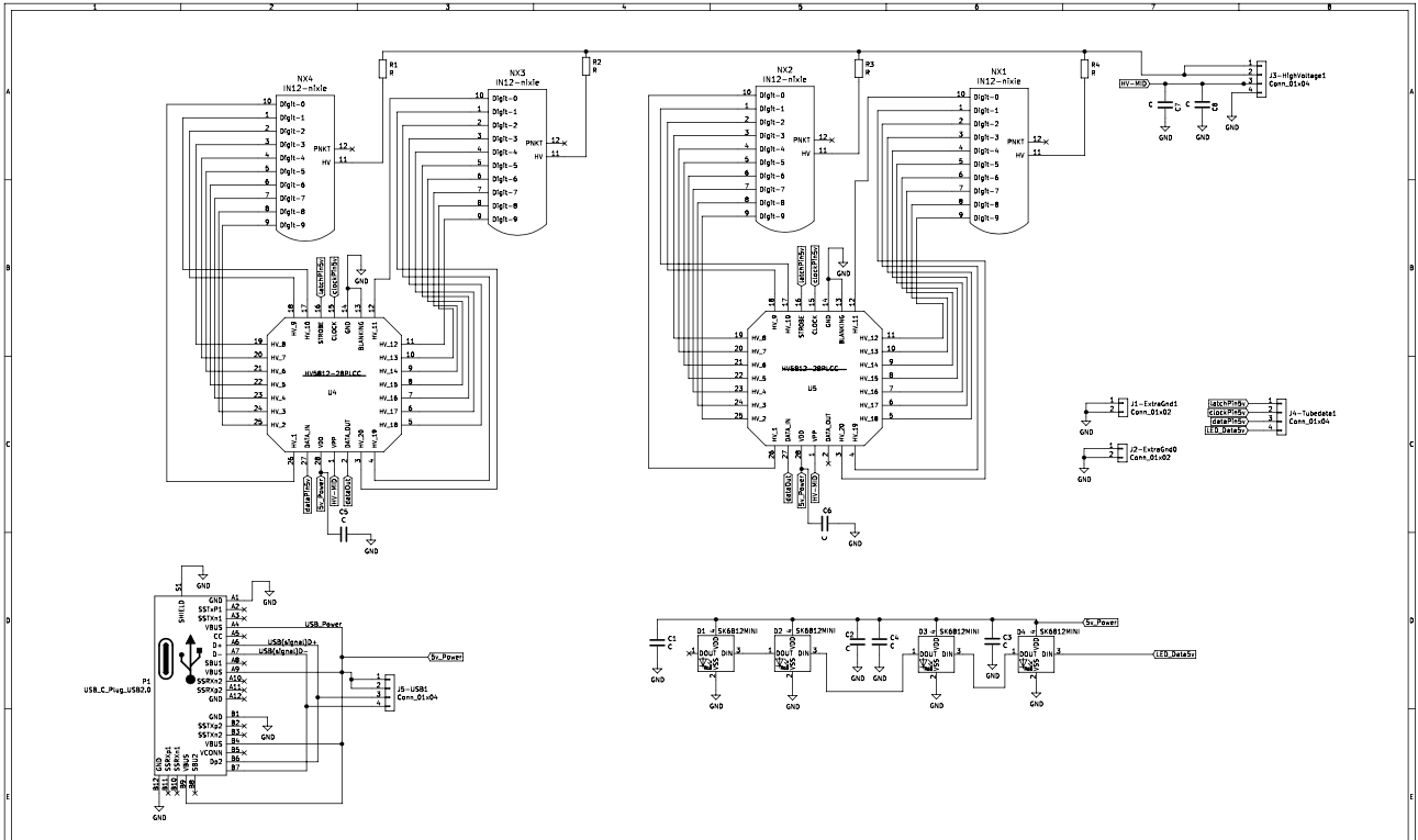
5. Circuit Schematics
Top board with microcontroller, power supplies, RTC clock chip, logic converters and sensors.
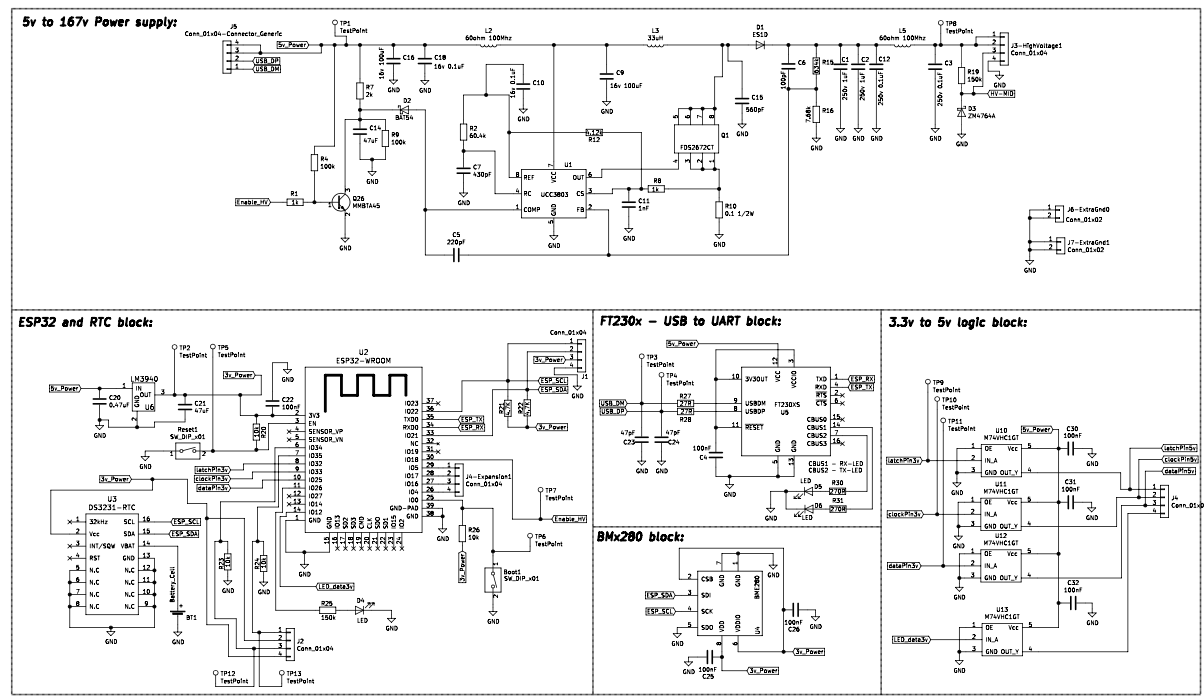
Bottom board with nixie tube sockets, USB-C connector, RGB LEDs and high voltage drivers.
Comments and Questions
9 Comments
Submit a Comment
Thank you all backers from Kickstarter – you are awesome!
JB Sherlock
Filip Bugajski
Fonz Row
Vincent Roux
Kento Koseki
Filip Bugajski
Caio Marcelo
Torkel Gjerde
Thaddée Girard
Peter Garelli
Joe Mendez
Mitchell Greenblatt
Daragh Regan
Zachary Williams
Chrisman cook
Claude Alain Sewer
Netanel Arad
Royce Tan
Naoki Kitajima
Gjert Bakkevold
Frank van Dorp
Walter Fraser
Joren Peeters
Michael Pentecost
Daniel Wesson
Rudolf Ditz
Kieran Clarke
Wanpiti Wattanapanich
Pon Sodprasert
Aaron Sturm
Tristan Tkachuk
Thomas Price
King Heiple
Ikhwan Salim Sujak
Lionel Teo
Abdulla Alsulaiti
Kelvin Tong
Joseph Gottlieb
Kimihiko Sugiyama
Rod Hoon
Joshua Alliance
Martin Weber
John Kim
Zachary Kugler
Stefan Schreck
Simon Boucher
Liam Healy
Dylan Cupedo
Keith Michel
Stefan Bohman
Andreas Dittfurth
Chehui Liao
Peter
Jakob Lindbjerg Buthler
Harry Hopkins
Théotime Bastin
Jonas Masetti
Philip Wagner
Alberto Schileo
Kuechler Christian
Roland Weiß-Ludwig
Mackie Wu
Dirk-WIllem van Gulik
Remo Stirnimann
Chris Waddington
Brian Kwak
Pia Kaufmann
Helle Kaufmann
Aaron Horowitz
Philipp Mathar
Thiago Viero
Nathan Lee
Emil
Ravipart
Takuji Sugiura
Damien Wright
John Elliott
The Creative Fund by BackerKit
The short about
Tordesign.net - The realization of a mixed process of engineering, design and the need of a mind to materialize something physical.

copyright © tordesign • 2017-2022 • all rights reserved



Hi Tor,
I received my clock yesterday. Beautiful design. Looks great! Worth the wait.
I just have a few questions. 1. Is there a way to change any of the time values WITHOUT having to reprogram the whole clock?
2. How can the date and temperature be programmed to display along with the time?
Thanks Again, Joseph Gottlieb
Hi Joseph,
Glad to hear that it arrived safely, and thank you for your kind words.
for your questions:
1. You can only change the setting of the clock as described under “Setting mode” here on the page tordesign.net/nixler. If you for example want to only display hour/minute and turn off the switching between hour:minute and seconds, this needs to be done in software/code.
2. Aha! so you might want to have the clock cycle through the date/temperature/pressure without pushing the button? – If you look at the latest source-code the temperature is read and displayed under the function “checkButtons” (on line 997 to 1040) so a modified version of this part would need to be implemented in the main loop. Same for pressure, date and year (line 1044 to 1108 in source code)
link to GitHub source code: Link
to install esp32
https://randomnerdtutorials.com/installing-the-esp32-board-in-arduino-ide-windows-instructions/
Thank you for pointing that out!
without the added step of including
https://dl.espressif.com/dl/package_esp32_index.json
under “additional Board managers URLs” from preferences in Arduino IDE,
the ESP32 is not available for installation. Updated the guide with this important step.
FT230x USB to UART chip driver for windows: https://www.ftdichip.com/old2020/FTDrivers.htm
FYI my com port did not show the name “usbserial-D308VW17”, but if you look in the device manager under the ports section and verify the driver is working you should be good. I was able to Upload anyways to my COM4 port.
True! In Windows the available peripherals shows up as COM.
Perfect Ponso 👍
I have downloaded TD_NIXLER_V_1_2 and tried to verifiy and compile in Arduino 1.8.16. I get an error from the setup and initialisation section for :
EEPROM.begin(EEPROM_SIZE);
I suspect that it is due to not having an EEPROM library but the “Includes” section does not specify which EEPROM library to use.
Hi Kieran,
Cool to know that you are diving into the code.
The EEPROM library should come with the Arduino installation.
However It might indeed be the case that its missing.
Could you copy and past the complete error message you get from compiling?
Disregard the above as I have gone back in to Arduino to capture the error message and it now verifies and compiles without any issues. Go figure. I will give loading V1.2 code a go and let you know how I get on.